
How It Works: Pressure Switch
THE PRESSURE SWITCH
The pressure switch is an important component on many of our electric models. It’s the electric counterpart to the piloted unloader valve which we discussed in a previous blog post. The following post will cover the primary components of a pressure switch, what it is, how it works and how to adjust one. While pressure switches are used in a number of applications, the following post will focus specifically on how they are used in the assembly and operation of an electric air compressor.
PRESSURE SWITCH COMPONENTS
Click photo to enlarge.
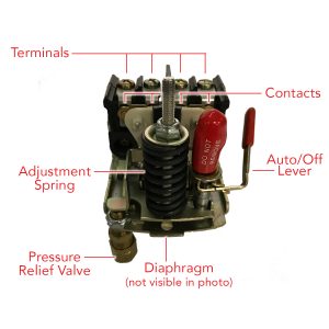
Auto/Off Lever (or Knob)
The lever (or knob, in a few cases) is used to manually separate the contacts. It should always be turned to the ‘off’ position before plugging in or unplugging the air compressor.
Terminals
The terminals are the points where the incoming and outgoing power leads are connected to the pressure switch.
Contacts
The contacts, which are made from a conductive material (90% silver, 10% nickel), are used to complete the electrical circuit and allow power to the motor. When separated, the circuit is broken and the motor will shut off.
Diaphragm
The diaphragm is made of a flexible material that pushes against the block as air pressure increases. When the specified ‘cut-out’ pressure is reached, it forces the contacts apart and shuts down the motor.
Pressure Switch Relief Valve
The pressure switch relief valve, which is located on the base of the pressure switch, is plumbed into the top of the check valve with a copper or nylon tube. When the pressure switch contacts separate, a lever actuates this valve to relieve pressure that was trapped between the pump and check valve.
Adjustment Spring(s)
The adjustment spring is used to increase and decrease the cut-in and cut-out pressure settings. Some pressure switches have a secondary spring (usually smaller than the primary spring) that will adjust the cut-out pressure without affecting the cut-in setting.
WHAT IT IS
A pressure switch is a mechanical device that relies on air pressure to control the operation of an electric air compressor. This simple mechanism completes the circuit and allows power to the motor as long as system pressure is below a specified setting. All of the pressure switches used on our air compressors include a pressure switch relief valve which relieves head and line pressure, allowing for easier starts.
HOW IT WORKS
We use several different pressure switches on our models. Each one is slightly different, but in all cases the basic operation follows this pattern:
With the air compressor plugged in, the user moves the lever to the ‘auto’ position, forcing electrical contacts inside the switch together to complete the circuit. Simultaneously, the motor starts and the air compressor begins to pressurize. When the specified system pressure is reached, a diaphragm inside the pressure switch pushes against a mechanism which forces the electrical contacts apart, breaking the circuit and stopping the motor. At the same time, the pressure relief valve opens and relieves back-pressure caught between the pump and check valve. As air is used and tank pressure drops to a specified ‘cut-in’ setting (approximately 30 PSI below the ‘cut-out’ setting) the contacts close and the motor starts again. The cycle continues as long is the air compressor is in use.
HOW TO ADJUST
Caution: Before performing work on any air compressor component, unplug the machine from the power source and drain all pressure from the system.
Many of our pressure switches include adjustment instructions on the inside of the cover. If your pressure switch does not have instructions, follow these steps:
Turn the primary spring clockwise to increase both cut-in and cut-out settings or counterclockwise to decrease them. If the pressure switch has a differential adjustment spring, the same principle applies. Clockwise will increase the differential and counterclockwise will decrease it.